The Gravitational
Catapult

A ground-based launch assist system that transfers the most energy-intensive phase of flight to permanent infrastructure, eliminating acoustic loads, thermal stress, and propellant waste at the moment of highest atmospheric density.

500 km/h
Exit Velocity Boost
Delivered to the vehicle before the first engine ignition
12
Structural Pillars
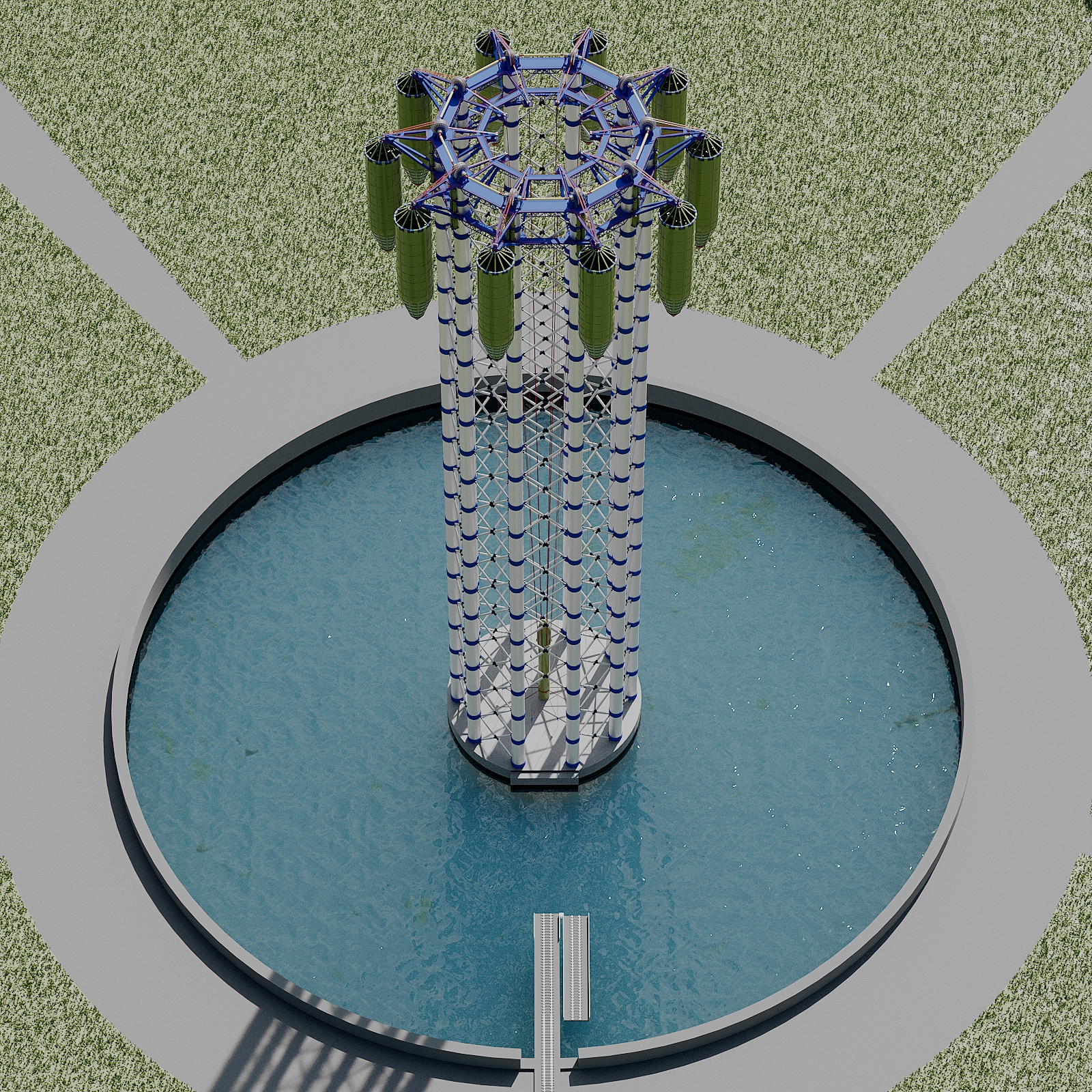
Above-ground guide tower configuration
300 m
Maximum Tower Height
Structural height of the above-ground guide framework
800 m
Underground Silo Depth
Subterranean acceleration channel, counterweight travel distance
Operating Principle

Gravity as the primary energy source

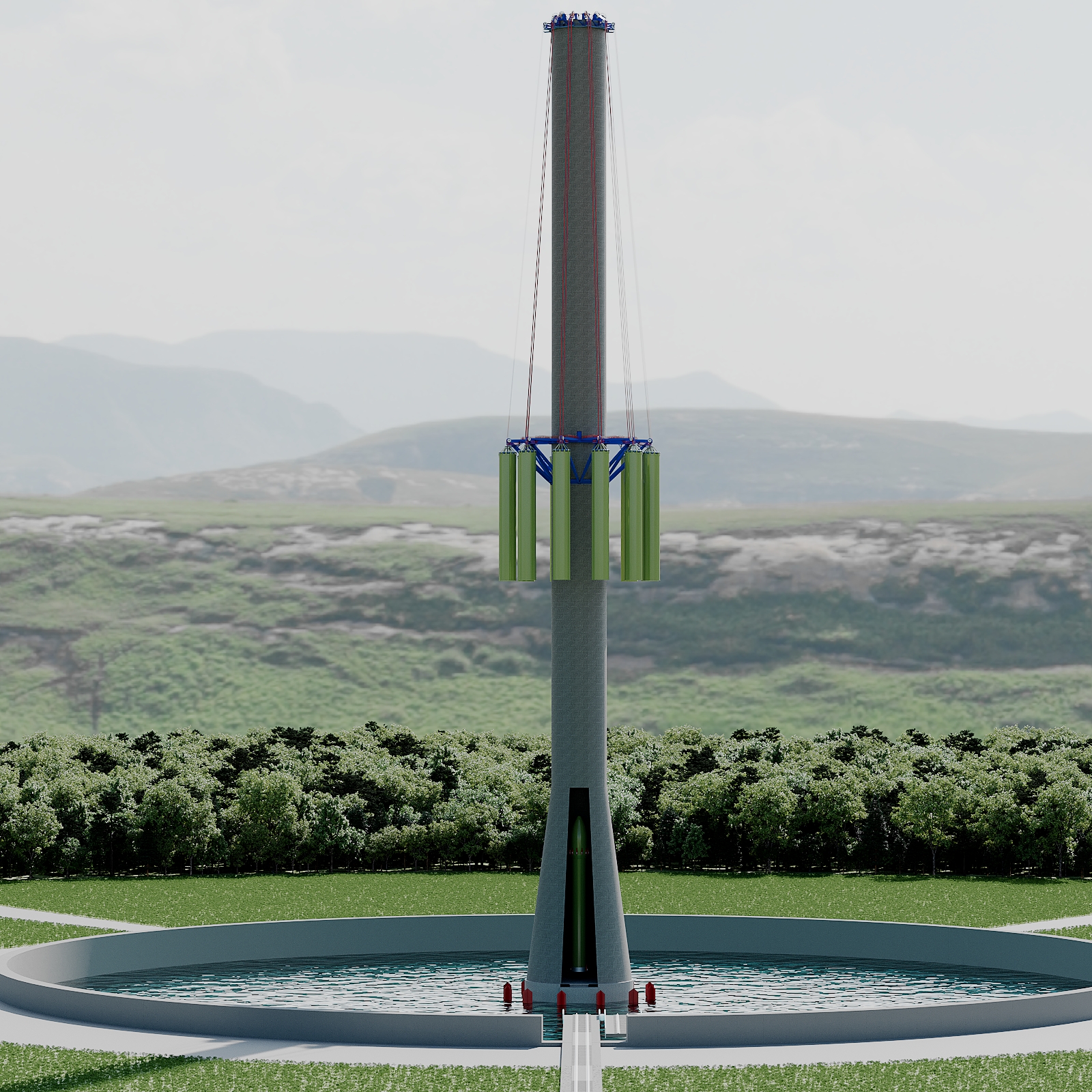
Before any engine ignites, the vehicle is already travelling at 500 km/h. Water counterweights, accumulated in large reservoirs at the top of the structure, fall under gravity through an 800-metre underground silo, pulling the rocket skyward through the twelve-tower guide framework.

The counterweight system resets automatically between launches, water is pumped back to the upper reservoir using off-peak grid electricity, or renewable sources co-located at the spaceport. No external energy is consumed during the launch event itself.

The 1.5-metre thick concrete walls of the Oceano launch cup absorb the acoustic energy that would otherwise destroy adjacent infrastructure. By the time engines ignite, the vehicle has already left the densest portion of the atmosphere.

Structural Design

Underground bunker architecture

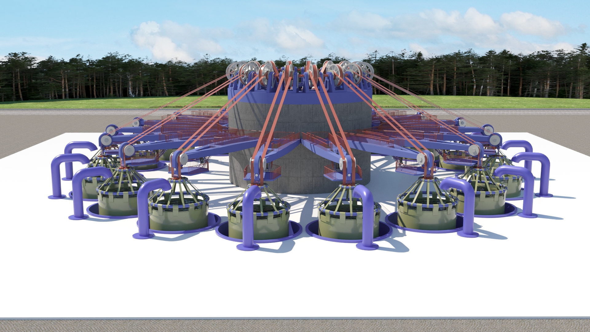
All massive winch mechanisms, the components subject to the greatest mechanical stress during a launch, are safely bunkerized in submerged, blast-proof underground concrete rooms. This design choice has two critical consequences.

First, structural maintenance is performed in a controlled, ground-level environment rather than at height. Second, any mechanical failure is contained underground, with zero risk of debris affecting the launch vehicle or adjacent facilities.

The above-ground towers serve only as trajectory alignment guides, they bear no dynamic load during the launch event and require no active maintenance between missions.

Technical Specification
Exit Velocity 500 km/h (139 m/s), constant exit velocity at the top of the guide structure. Delivered to the vehicle before the first engine ignition.
Silo Geometry 800 metres depth, vertical axis, concrete-lined. The Oceano launch cup at the base features 1.5-metre reinforced walls designed to contain acoustic energy and direct thrust vertically.
Guide Framework 12 pillars, maximum height 300 metres, arranged in a circular configuration around the silo aperture. Provides trajectory alignment without bearing dynamic launch loads.
Counterweight System Water-based, gravity-replenished, requiring no external power during the launch event. Reset cycle via pump: compatible with off-peak grid or co-located renewable energy. Counterweight mass is sized to the vehicle's gross launch weight.
Winch Bunkers Blast-proof underground concrete rooms, all mechanical drive components are submerged below grade. Zero above-ground mechanical exposure. Maintenance access via dedicated underground corridors.
Acoustic Isolation The underground silo geometry directs acoustic energy downward and into the launch cup walls. Above-ground acoustic load during the assist phase: zero (vehicle is unpowered). Engine ignition occurs at altitude, after clearing the guide structure.
Payload Benefit The 500 km/h pre-launch velocity directly reduces the delta-v requirement from the propulsion system. Combined with the fuel recovered by eliminating hover-landing, this recovers an estimated 15-23% additional payload mass per mission.
Facility Footprint The above-ground structure occupies a diameter of approximately 200 metres. The underground components are fully contained within the silo footprint. No flame trench, no water deluge system, no pad refurbishment cycle.
System Diagram
GRADE 800 m SILO WINCH BUNKER H₂O COUNTERWEIGHT 300 m 800 m 1.5m CONCRETE WALLS (OCEANO CUP) 500 km/h before engine ignition
Technical Breakdown

27 reasons the catapult works

The main page states the case in one sentence: the catapult saves fuel and removes load from the launch pad. This section goes further. Each point below is a separate, independently verifiable consequence of the same system. Points 1-8 follow directly from physics. Points 9-24 are sound inferences based on documented industry precedent. Points 25-27 are economic consequences that depend on specific implementation, presented as justified potential, not guaranteed outcomes.

Gravitational catapult tower
I: Physics and Flight Energy

What the catapult actually changes in the rocket equation

Not as a slogan, as a calculated effect.

01
Payload gain exceeds the velocity fraction saved
The Tsiolkovsky equation is exponential. A 300 km/h head start translates to roughly 44% more payload at the same fuel load. At 500 km/h, the gain is larger still.
02
Bypasses the most wasteful phase of flight
The greatest velocity losses occur in the first seconds after liftoff, when thrust barely exceeds weight and the vehicle is nearly stationary. The catapult exits this phase using counterweight energy, not propellant.
03
Engine ignition in favorable conditions
Ignition happens at speed and altitude, not static at ground level. Part of the climb through the densest atmosphere is already complete before any fuel burns.
04
Variable exit velocity without hardware changes
The same tower and fixed acceleration profile delivers different exit speeds by releasing the vehicle at different points in its travel. One system, multiple configurations.
05
Multi-stage mechanical differential
Variable-radius drums provide a continuously changing gear ratio with no electronics or hydraulics. Counterweight energy is distributed evenly across the full acceleration stroke.
II: Structural Loads on the Vehicle

A gentler load regime than the vehicle already handles

Catapult acceleration is not a new problem for a thin-walled tank. It is a milder condition than what the tank must already survive.

06
Tension instead of compression
Rocket engines push from below, axial compression, where thin-walled shells risk buckling. The catapult pulls from above, axial tension, where buckling simply does not occur.
07
Compatible with thermal blanket, not ceramic tile
Ceramic tiles cracked from vibration and point loads. An elastic thermal blanket handles tensile and vibration loads as a flexible material without accumulating microcracks.
08
Acceleration within the vehicle's normal operating range
The 3-4g working range matches loads the vehicle already must survive at engine burnout. The catapult introduces nothing structurally new to the design.
III: Reliability and Failure Character

Not fewer failures, a safer kind of failure

The critical distinction is what a failure looks like on the earliest segment of flight.

09
Cold failure and hot failure are separated
While the vehicle travels through the catapult, the engines are not running. A failure on this segment is a mechanical event, no fire, no explosion of a fueled vehicle on the infrastructure.
10
Infrastructure survives vehicle failure
A vehicle breakdown primarily damages exposed elements, cables and straps, replaceable in hours, not the capital structures protected underground.
11
Reduced bottom heating of engines
Multi-engine clusters reflect plume back onto the tail section when launching from a pad. Ignition away from any reflecting surface sharply reduces this effect, extending nozzle service life.
12
Less foreign object debris in turbopumps
A plume hitting a static pad at zero speed lifts dust and debris, a documented source of turbopump damage in reusable operations. Airborne ignition eliminates this debris source entirely.
13
Standardized ignition conditions
Ground starts must handle wind, thermal shifts, and pad turbulence. Ignition at a known catapult exit speed standardizes conditions from one launch to the next.
14
Emergency braking potential before ignition
If braking capability is designed into the drum and cable system from the start, some early-phase failures become recoverable rather than total losses.
Aerial view of catapult tower Counterweight mechanism
IV: Launch Infrastructure

Entire cost categories that stop existing

The catapult does not reduce pad costs. It eliminates categories of them.

15
No acoustic and vibration load on the pad
The worst phase for engines and electronics is the first seconds after ignition, when the plume reflects back off the table. Moving ignition away removes this problem geometrically, not by compensation.
16
No launch table as a structural element
No metal structures in the plume path means no melted concrete, no flame reflection, and no accumulation of explosive gas under the vehicle during fueling.
17
No water deluge system
Thousands of tonnes of water per launch for acoustic suppression represent an entire engineering system, eliminated along with its maintenance, plumbing, and inspection regime.
18
No pad refurbishment between launches
A heavy launch regularly leaves the pad requiring days or months of inspection and repair. With airborne ignition, this cost and downtime disappears.
19
Lower construction cost and faster build time
Standard concrete columns and winch mechanisms build faster and cheaper than a launch table with flame trench and deluge system.
20
Automated ground handling
The winch and drum system moves and positions the vehicle across the pad without heavy cranes, functioning as a universal automated handling system for the entire facility.
V: Operations and Turnaround

How the rhythm of the spaceport changes

Not just the physics of one launch, the operating tempo of the facility.

21
Turnaround drops from weeks to hours
No thermal infrastructure damage, no pad refurbishment. The cycle between launches compresses from weeks or months to hours.
22
High launch cadence from a single pad
Short turnaround means many more launches per year from one facility, without building duplicate infrastructure.
23
Fewer support personnel required
A mechanized, standardized cycle requires fewer people and fewer manual operations than classical pad preparation before every launch.
24
Longer engine service life
Fewer cycles in reflected plume and ground thermal conditions means longer time between engine overhauls, a direct operating cost reduction.
VI: Economics

How the engineering converts to money

Where the case is strong and where it still requires real-world confirmation.

25
Payload increase is direct revenue
Every percent of additional payload at the same launch mass is direct income per mission. Not abstract engineering elegance.
26
Reduced capital cost of the spaceport
No pad, no deluge system, no refurbishment, cheaper construction: the combined saving cuts facility capital cost by a multiple compared to a classical launch complex.
27
Potential reduction in insurance costs
The more predictable, mechanical character of early-ascent failures may provide grounds for reconsidering risk premiums on that flight phase. This requires a separate conversation with insurers, but the premise is sound.

Where each point stands

Points 1-8 follow directly from physics and mechanics. They are calculated explicitly and verifiable by independent analysis.

Points 9-24 are sound engineering inferences based on documented industry precedents: bottom heating in multi-engine clusters, infrastructure destruction in pad failures, and real costs of capital construction.

Points 25-27 are economic consequences that depend on specific implementation, production volume, and insurance market negotiations. We present them as justified potential, not guaranteed outcomes.