Active Capture
Trap

A paradigm shift in vehicle recovery: instead of forcing rockets to burn propellant achieving near-zero descent speeds, we deploy infrastructure that moves to meet the vehicle, at speed, without hesitation.

23 t
Fuel Saved Per Launch
Maximum propellant mass recovered per mission vs. hover-landing
20 m/s
Tracking Cart Speed
Maximum velocity of active pursuit carts
5-7 m/s
Intercept Velocity
Vehicle speed at point of cable contact and hydraulic engagement
200×200m
Working Zone
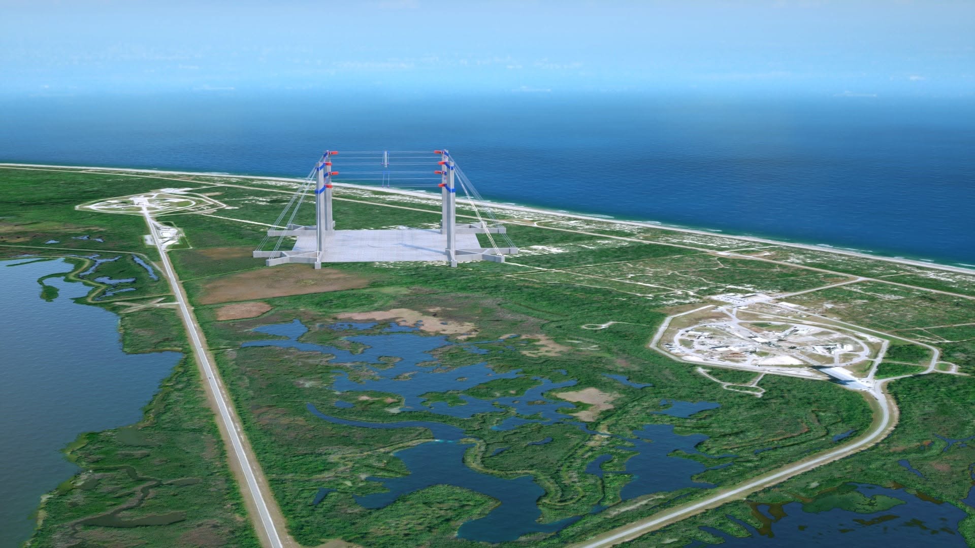
Total capture area served by the 8-tower configuration
The Paradigm Shift

Stop burning propellant to stop

Every rocket that hover-lands must reserve a substantial fraction of its propellant budget not for reaching orbit, but for the return journey, specifically for the final, fuel-intensive deceleration from terminal descent velocity to zero.

This is a structural inefficiency. The fuel consumed in the last few hundred metres of descent could have been orbital payload. Dahir Uzay eliminates this constraint entirely by deploying infrastructure that absorbs the kinetic energy the vehicle would otherwise have to burn away.

The result: the vehicle arrives cold, engines off, falling. The capture system meets it.

3-Tier Guidance System

Precision at terminal velocity

Capturing an unpowered vehicle requires a multi-layer guidance architecture. The Dahir Uzay capture system uses three tiers, each progressively finer in resolution as the vehicle approaches.

Tier 1: Coherent Radar: long-range tracking establishes vehicle position and trajectory from 10km altitude, feeding real-time data to the cart positioning system.

Tier 2: Laser Guidance: from 500m, laser rangefinders lock onto the vehicle's base and provide centimetre-level positioning for final cart alignment.

Tier 3: Contact Sensors: cable tension sensors at the moment of engagement confirm contact and trigger hydraulic dampener activation in under 8 milliseconds.

Technical Specification
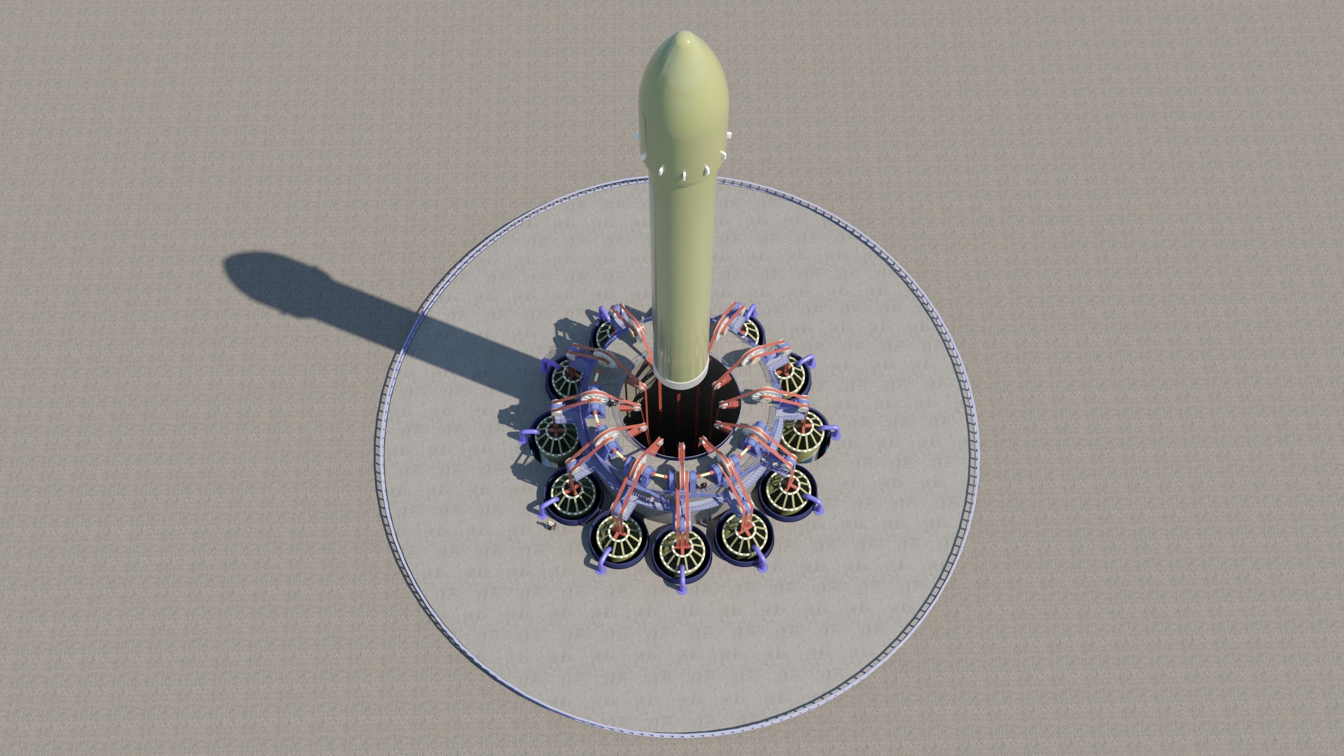
Tower Configuration 8-pillar arrangement surrounding the 200 × 200 metre working zone. Towers are positioned at the four corners and four midpoints of the capture perimeter.
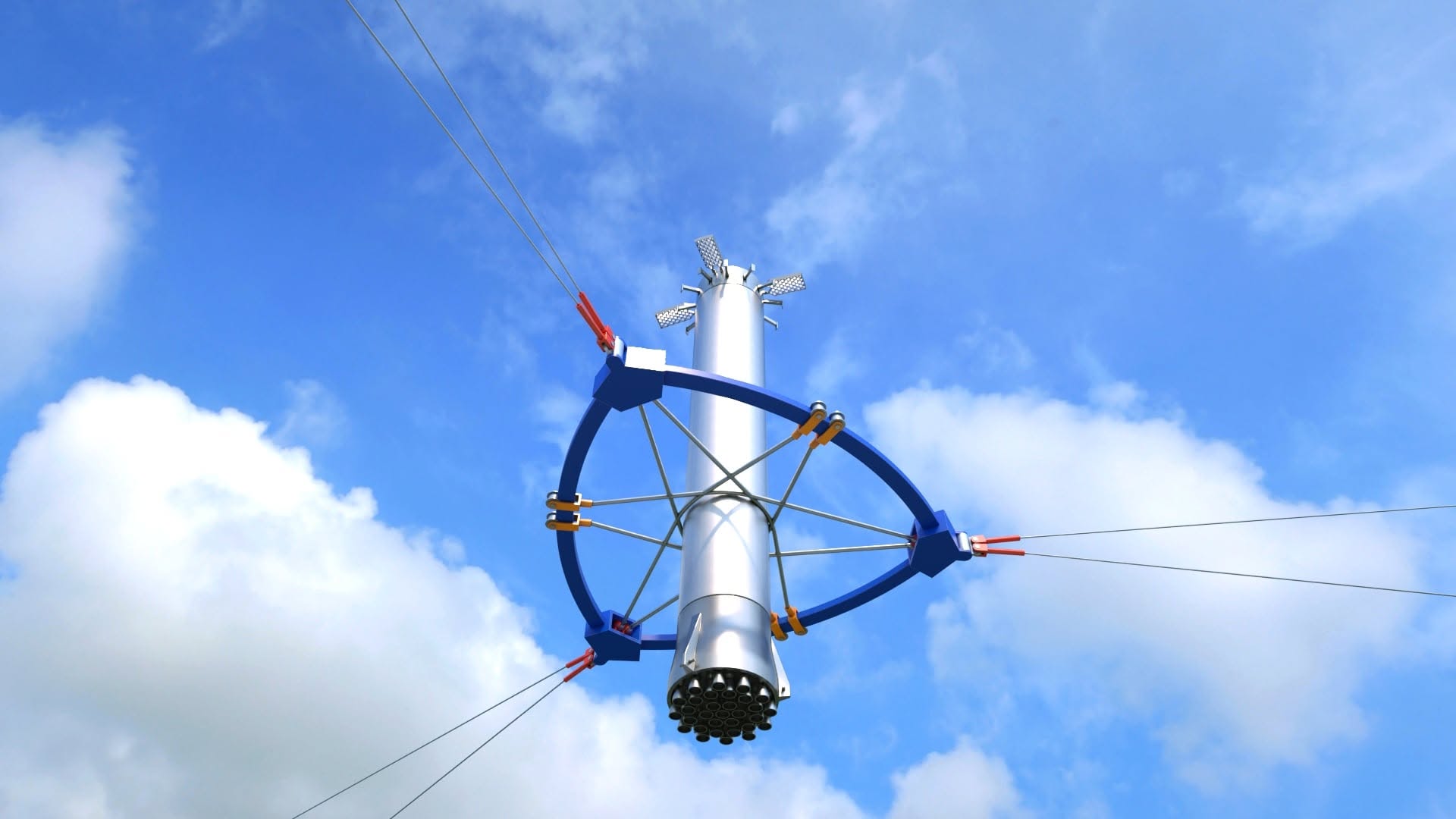
Cable Network Hydraulically tensioned cables span between towers and terminate at tracking carts on each tower's vertical rail system. Cable tension is dynamically adjusted during the approach phase.
Tracking Carts One cart per tower, rail-mounted on the inner face. Maximum travel speed: 20 m/s. Carts receive positioning commands from the Tier 2 laser guidance system and close on the predicted intercept point before vehicle arrival.
Intercept Protocol Vehicle is intercepted at 5-7 m/s descent speed, well below terminal velocity. At this speed, the cable engagement loads are within the structural envelope of the vehicle's hard-point attachment system.
Hydraulic Dampeners Each tower contains a multi-stage hydraulic dampener array sized to absorb the vehicle's residual kinetic energy at intercept velocity. Energy absorption rate is variable, dampeners modulate in real time based on contact sensor feedback to prevent structural shock.
Propellant Zero No engine throttling, no hover phase, no landing burn. The vehicle arrives with zero propellant consumption from the moment of orbital insertion de-orbit burn until next ignition. All deceleration is absorbed by the capture infrastructure.
Turnaround Window Capture to relaunch in under 8 hours, no pad damage to repair, no engine cooldown to wait for, no acoustic fatigue to assess. The tower cables reset to ready position in under 4 minutes after each capture.
Guidance Tiers Coherent radar (long range) → laser rangefinder (mid range, centimetre precision) → contact sensors (engagement confirmation, <8ms response). Three independent systems provide full redundancy at each phase.
System Diagram
200 × 200 m WORKING ZONE T1 T3 T2 T7 T5 T6 T8 T4 ↓ 5-7 m/s engines off CART CART 20 m/s 20 m/s TIER 1 Coherent radar TIER 2 Laser guidance TIER 3 Contact sensors
Technical Breakdown

51 reasons the capture trap works

Aerial view of capture trap facility

The main page makes a single claim: the trap lets the vehicle arrive with engines off. This section unpacks every engineering consequence of that choice. Points 1-19 follow directly from the mechanics and thermal design of the system. Points 20-32 are sound inferences based on documented precedent. Points 33-44 depend on specific facility implementation. Points 45-51 extend the principle beyond a single Earth-based pad.

I: Geometry and Capture Accuracy

The vehicle does not need to hit a point. The system moves to meet it.

The fundamental shift from passive to active recovery.

01
Large, movable capture zone
The working area spans hundreds of square metres vs. centimetres in passive systems. When the vehicle drifts laterally, the capture zone moves to meet it, compensating for aerodynamic error and wind drift.
02
Adapts to different vehicle geometries
Real-time cable length adjustment accepts vehicles of different diameters and configurations without mechanical retooling. Reconfiguration between missions is a software operation.
03
No dead zones in the working area
Within the column perimeter, the system provides continuous 3D access with no restricted zones imposed by a rigid tower structure.
04
Software precision, not structural precision
Positioning calibrates against actual cable positions, not absolute foundation coordinates. Ground settlement and thermal expansion of supports do not accumulate as positioning error.
05
Capture at non-zero descent speed
The system receives a vehicle with meaningful residual velocity and decelerates it over a controlled braking distance. No requirement for near-zero speed at the moment of contact.
II: Energy Absorption Mechanics

How the system converts the vehicle's speed into tension, not damage

The kinetic energy of descent is absorbed across distance, not in a single impact.

06
Software-adjustable stiffness
The control algorithm transitions from elastic-capture mode at first contact to rigid-lock after stabilization. This eliminates the shock loads typical of rigid mechanical docking systems.
07
Distributed kinetic energy damping
Deceleration is the combined braking work of all winches over an extended distance, not a single impact. Heavy vehicles can be received within comfortable structural load limits.
08
Safe, even body contact
Cables wrap evenly around the vehicle circumference, eliminating point-load penetration risk to the tank wall. Top-down capture prevents tip-over even with a failed landing leg.
09
Torsional oscillation suppression
Wide column spacing creates significant leverage to counter axial rotation of a large-diameter vehicle in crosswind, without additional hardware.
10
Centre-of-mass shift compensation
Tension sensors detect load asymmetry in real time. The system automatically redistributes cable tension to level the vehicle during capture.
11
Active pendulum damping
Controlled winches damp vehicle swing within one or two oscillation periods. The vehicle does not continue swinging once it is secured.
12
Clearance safety margin
A vehicle at the centre of the working zone has tens of metres of clearance to the nearest column. Contact with structure is not possible even with significant approach deviation.
III: Thermal and Mechanical Drive Isolation

Why cables in a heat zone outperform precision mechanics in the same zone

Everything expensive is kept far from everything hot.

13
Drives kept remote from the heat zone
All winches and motors sit on distant columns, well away from the capture point. No direct contact with engine plume on final descent.
14
Thermal inertia of working elements
The only elements exposed to potential heat are ceramic-shielded cables, no precision components, no heat-sensitive bearings, nothing that can seize.
15
No precision mechanics in the working zone
No linear bearings or ball screws that can jam from heat or contamination. The same property makes this system viable in dusty environments, including lunar and Martian surface operations.
16
Aerodynamic transparency
A cable structure has no solid surfaces and creates no turbulence on approach. The vehicle arrives in calmer airflow than when approaching a solid tower.
17
Seismic isolation of foundations
Flexible cables isolate column foundations from capture vibration, extending the service life of permanent ground infrastructure.
18
Algorithmically defined effective mass
Cable tension control makes the system behave as a near-weightless trap at first contact and a rigid lock after stabilization. Same hardware, different software state.
19
Mobile fire suppression along cables
Nozzles mounted on cables direct suppressant directly to the vehicle body, moving with it rather than staying at a fixed point on the ground.
IV: Reliability and Redundancy

What happens when something goes wrong

Not theoretical failure modes, specific failed components and what comes next.

20
Multi-level redundancy
Multiple independent layers of capture elements operate simultaneously. Individual winch or cable failures do not abort the capture operation.
21
Guaranteed intercept at critical fuel margin
The control algorithm is designed to catch the vehicle seconds before calculated tank depletion, reducing loss risk from unexpected fuel overuse in the final descent phase.
22
Full visual access to vehicle state
A suspended vehicle exposes all its components to simultaneous multi-angle camera inspection, with none of the access limitations imposed by a classic launch tower structure.
23
Multi-tier sensor guidance system
Different measurement principles at different ranges, long, mid, and final metres, with overlapping zones ensure no gap when handing off between guidance tiers.
V: Testing and System Development

The ability to learn without risking a real vehicle

Almost no landing system can be tested this way. This one can.

24
Low-cost right to fail during development
The system can be trained and tested without a rocket, without propellant, and without financial risk. A helicopter and a correctly sized, weighted test mass are sufficient.
25
Deliberate failure scenario training
Test masses can be dropped with rotation, lateral drift, or simulated structural damage, training the system on exactly the off-nominal situations that cannot be safely created with a real vehicle.
26
High-fidelity digital twin and rapid test cycles
The relatively simple cable mechanics allow high agreement between model and reality. No structural shock to foundations at each drop means many tests per day are practical.
VI: Economics and Payload

How removing landing propellant converts directly into cargo

Every kilogram the vehicle does not need to carry for its own landing is a kilogram available for the customer.

27
More commercial payload per launch
Eliminating landing propellant, landing legs, and heavy launch infrastructure converts directly into additional cargo capacity at the same launch mass.
28
Structural weight savings
Smaller propellant reserves and no landing legs allow lighter tanks and adjacent structural elements, creating additional mass margin available for payload or fuel.
29
Turbopump life extension
Eliminating the re-ignition and landing burn removes the most thermodynamically severe engine running hours, extending time between overhauls.
30
No thermal loads on structure at landing
No running engines at capture means no reflected plume heating the base of the vehicle, and no infrared interference with optical and radar guidance during the final approach.
31
Low upgrade cost for heavier vehicles
Moving to a heavier or larger vehicle requires cable replacement and a software update, not rebuilding a capital tower. Fundamentally cheaper than modifying any rigid mechanical capture system.
32
Insurance cost reduction through accumulated test data
Many inexpensive tests mean that by first real launch, the system has far more validation data than any system testable only on actual vehicles. A large validation dataset is direct grounds for risk premium revision.
Rocket held in capture trap Top-down view of capture ring
VII: Infrastructure and Operations

How the facility itself changes

Not just the physics of a single capture, the daily operating tempo of the pad.

33
No landing pad cooling systems
No direct contact of hot landing legs with concrete means no pad cracking, no melting, and no periodic surface replacement.
34
Automated pad transport
The winch system moves the vehicle across the full facility perimeter without heavy cranes, functioning as a universal automated handling system.
35
Fuel type agnostic
The open cable architecture imposes no structural constraints on propellant line routing, cryogenic or storable fuels, any configuration.
36
Environmental durability
Minimal wind load at standby, ice resistance, thermal self-regulation of columns, and sealed components resistant to marine corrosion give the system a wide operating weather envelope.
37
Fast vehicle evacuation from the capture zone
Synchronizing capture with transport platform arrival enables immediate vehicle evacuation and servicing start within minutes of contact.
38
Minimal ground footprint
Columns occupy small area at base, leaving all space under the cables free for ground vehicles and logistics, unlike the solid foundation of a classic launch complex.
39
Construction tolerances, not machining tolerances
Support columns do not need precision positioning at installation. Multi-metre deviations are acceptable, final accuracy is provided by software cable control, not structural geometry.
40
Integrated weighing at capture
Cable tension sensors determine the exact weight and centre of gravity of the returned vehicle during the capture itself. No separate weighing step required.
41
Crane function between captures
Between vehicle arrivals the same winch system functions as a cargo crane for container movement and equipment installation across the pad.
42
Flexible landing point within the perimeter
The system can receive a vehicle anywhere inside the working zone, not only at the geometric centre. Operational even if the central area is locally damaged or temporarily obstructed.
43
Clean radio spectrum
Perimeter-spaced columns do not form an extended metal screen. Less interference with telemetry and vehicle communications on approach than a solid tower.
44
Sensors above the smoke layer
Measurement equipment at column tops sits above the smoke and soot from vehicle capture, preserving measurement quality exactly when it matters most.
VIII: Resilience and Protection

Why an open cable system is harder to put out of action than a closed tower

Damage does not mean loss of the facility.

45
Critical equipment underground
Winch mechanisms, drives, and computing systems can be placed in protected underground modules under reinforced concrete. The most expensive components are not exposed.
46
Natural electronics shielding
Underground placement of computing and power systems provides natural electromagnetic interference protection without additional specialist measures.
47
Isolated failure and fast recovery
Cables are the only truly exposed element. If damaged, they are replaced, not the expensive protected mechanisms below. Post-incident repair is incomparably faster than restoring a capital landing tower.
48
No cascade failure
One column or cable failure does not take the whole system down. Remaining components retain functionality through multi-level redundancy (see point 20).
IX: Scalability and Environmental Impact

Where this principle can go beyond a single Earth pad

The same control logic scales in two directions: larger vehicles and further destinations.

49
Scales to super-heavy vehicles
The structural mass of the capture system grows linearly with vehicle mass. Classic landing leg mass grows non-linearly, faster than vehicle mass itself. The advantage is largest for the heaviest vehicles.
50
Orbital and interplanetary scalability
Cable capture kinematics scale to large orbital module docking, active debris removal, and eventually landing infrastructure beyond Earth, with the same control principle throughout.
51
Reduced acoustic and environmental footprint
No running engines at the moment of capture itself, and no water deluge systems, reduce the noise and environmental impact of the capture pad vs. propulsive landing.

Where each point stands

Points 1-19 follow directly from the mechanics and thermal design of the capture system, logically derived from its structure and verifiable by analysis.

Points 20-32 are sound engineering inferences based on known precedents: redundancy in critical systems, test economics without flight hardware risk, and engine life at different load regimes.

Points 33-44 are operational and infrastructure benefits that depend on specific facility implementation, grounded in the same principle: open cable architecture vs. solid capital structure.

Points 45-51 represent potential that extends beyond a single Earth-based pad, protection from external events, environmental impact, and scalability to orbital and interplanetary operations. These require separate analysis for each specific application before becoming part of a financial model.